0

Out of 0 Ratings

Owner's of the iOptron Camcorder Accessories iOptron Camcorder Accessories gave it a score of 0 out of 5. Here's how the scores stacked up:
  • Reliability

    0 out of 5
  • Durability

    0 out of 5
  • Maintenance

    0 out of 5
  • Performance

    0 out of 5
  • Ease of Use

    0 out of 5
of 46
 
16
STEP 6.Balancing the Payload
After attaching the scope and accessories, the mount head assembly must be balanced in both the
R.A. and DEC axes to ensure minimum stress on the mount driving mechanism.
WARNING: The telescope may swing freely when the R.A. or DEC Gear Switch is
disengaged. Always hold on to the telescope assembly before releasing the Gear Switches
to prevent it from swinging, which can cause personal
injury and/or equipment damage.
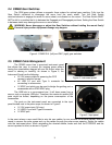
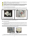
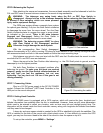
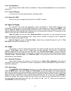
The CEM gear system utilizes a magnetic force system
for optimal gear meshing. Fully turn the Gear Switch clockwise
to disengage the worm from the worm wheel. Turn the Gear
Switch counterclockwise to engage the worm to worm wheel,
as indicated on the mount. There is NO state between
Engaged and Disengaged. Setting the Gear Switch in
between states may damage the worm or worm wheel.
WARNING: The balancing process MUST be done
with Gear Switch at the Disengaged position!
Otherwise it might damage the worm system.
With the corresponding Gear Switch disengaged,
balance the assembly in R.A. axis by moving CW along its shaft. Balance in DEC axis by moving the scope
with accessories back and forth in the mount saddle or within the scope mounting rings.
Only balance one axis at a time and start with the DEC axis first. Double check the mount to make
sure both the R.A. and DEC axes are balanced.
Return the mount to the Zero Position after balancing; i.e., the CW Shaft points to ground, and the
telescope tip is at its highest position.
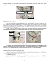
Set both Gear Switches to engaged positions after
balancing the mount. To make sure the gears are meshed
properly, gently turn the Gear Switch counterclockwise all
the way until you feel the resistance, but not over
tightening. You may back out 1//8 turn if the gear is not
moving smoothly.
STEP 7. Connecting Cables
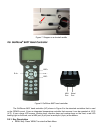
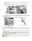
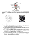
Plug in a 12V DC power supply to the DC12V POWER
socket. Connect the Go2Nova
®
8407 Hand Controller to the
HBX port on the mount side panel.
STEP 8. Setting Hand Controller
The CEM60 mount is equipped with a GPS receiver, which will receive the time, longitude and
latitude information from satellites after the link is established. However, there are still some parameters
which need to be entered to reflect your location, such as time zone info and daylight saving time. The
information will be stored inside the hand controller memory along with longitude and latitude coordinates
until they need to be changed.
A clear sky and open space outside is needed for the GPS to establish its link with the satellites. The
GPS is installed on the side of the mount with a black plastic cover. If it has difficulty to receive the GPS
signal, you may turn the mount head to the side of the mount to clear the space on top of it.
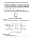
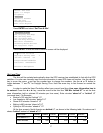
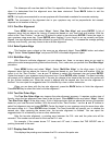
To set up the controller, press MENU =>“Settings”:
Figure 19. Gear switches
Gear switch
Figure 20. Connecting the cables
17
Press ENTER and select “Set Time & Site
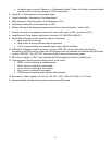
Press ENTER. A time and site information screen will be displayed:
Set Local Time
The time will be updated automatically when the GPS receiver has established its link with the GPS
satellites. You also can manually input the time information in case GPS does not function. Use the ◄ or ►
key to move the cursor _ and use the number keys to change the numbers. Use the or button to
toggle between “Y” and “N” for Daylight Saving Time. Hold the arrow key to fast forward or rewind the
cursor.
In order to make the Hand Controller reflect your correct local time, time zone information has to
be entered. Press the ◄ or ► key, move the cursor to the third line “300 Min. behind UT” to set the time
zone information (add or subtract 60 minutes per time zone). Enter minutes ahead of or behind” UT
(universal time). For Example,
Boston is 300 minutes “behind” UT
Los Angeles is 480 minutes “behind” UT
Rome is 60 minutes “ahead of” UT
Beijing is 480 minutes “ahead of” UT
Sydney is 600 minutes “ahead of” UT
All the time zones in North America are behind UT, as shown in the following table. So make sure it
shows “behind” instead of “ahead of” UT.
Time Zone Hawaii Alaska Pacific Mountain Central Eastern
Hour behind UT -10 -9 -8 -7 -6 -5
Enter Minutes 600 540 480 420 360 300
2014-03-09 10:19:18
Daylight Saving Time Y
300 Min. behind UT
Longitude:W071d08m50s
Latitude: N42d30m32s
Northern Hemisphere
Set Time & Site
Set Display and Beep
Set Guiding Rate
Set Tracking Rate
Set Parking Position
Meridian Treatment
Tracking Below Horizon
Set Eyepiece Light
Select and Slew
Sync. to Target
Alignment
Settings
Electric Focuser
PEC Options
Telescope Motion
Edit User Ob
j
ects
18
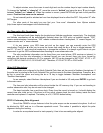
To adjust minutes, move the cursor to each digit and use the number keys to input number directly.
To change the “behind” or “ahead of” UT, move the cursor to “behind” and using the ▲ or ▼ key to toggle
between “behind” and “ahead of”. When the number is correct, press ENTER and go back to the previous
screen. Fraction time zone can be entered.
Do not manually add or subtract an hour from displayed time to reflect the DST. Only select “Y” after
DST begins.
For other parts of the world you can find your “time zone” information from iOptron website
(http://www.ioptron.com/support.cfm?module=faq#).
Set Observation Site Coordinates
The third and fourth lines display the longitude and latitude coordinates, respectively. The longitude
and latitude coordinates will be automatically updated when the GPS picks up satellite signals. “W/E”
means western/eastern hemisphere; “N/S” means northern/southern hemisphere; “d” means degree; “m”
means minute; and “s” means second.
If, for any reason, your GPS does not pick up the signal, you can manually enter the GPS
coordinates. Press the ◄ or ► key to move the cursor and using the ▲ or ▼ key to toggle between “W”
and “E”, “N” and “S”, and using the number key to change the numbers. It is always a good idea to do your
home work to get the GPS coordinates before traveling to a new observation site.
The site coordinates information can be found from your smart phone, GPS receiver or internet. In
case you only find the site information in decimal format you can convert them into d:m:s format by
multiplying the decimal numbers by 60. For example, N47.53 can be changed to N47º31'48”: 47.53º = 47º
+0.53º, 0.53º=0.53x60'=31.8', 0.8'=0.8x60"=48". Therefore, 47.53º=47º31'48" or 47d31m48s.
Select N/S Hemisphere
If the polar axis is aligned to the North Celestial Pole, then set the mount to Northern Hemisphere. If
the polar axis is pointing to the South Celestial Pole, set the mount to Southern Hemisphere. Press the ◄ or
key to move the cursor and using the or ▼ key to toggle between “Northern Hemisphere” and
“Southern Hemisphere”.
As an example, select Northern Hemisphere if you are located in US and press ENTER to go back
to the main menu.
The time and site information will be stored inside the HC memory chip. If you are not traveling to
another observation site, they do not need to be changed.
The hand controller has a real time clock. Every time the mount is turned on, it should display the
correct time after initial set up. If the time is off too much, please check the clock battery inside the hand
controller and replace it if required. The battery is a 3V, CR1220 button battery.
STEP 9. Performing Polar Alignment
One of the CEM60’s unique features is that the polar scope can be accessed at anytime. It will not
be blocked by DEC axle as in a German equatorial mount. This makes it possible to adjust the polar
alignment during the tracking.
In order for an equatorial mount to track properly, it has to be accurately polar aligned.
null
  • Add more products to collection
  • Add more products to collection
  • Add more products to collection
  • Add more products to collection
  • Add more products to collection
  • Add more products to collection
  • Add more products to collection
-

Find a Product